


Special requirements for periodical inspection of drying cylinders for paper making
1. general principles:
1.1 The comprehensive inspection of cast iron drying cylinder shall be carried out in accordance with the "General Process for Periodic Inspection of Pressure Vessels" and the special requirements.
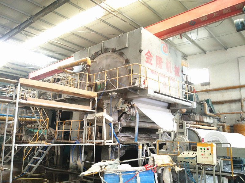
1.2 Objective: Cast iron dryer is widely used in paper industry. As the main material of cast iron dryer, gray iron has low strength and poor plasticity. In order to carry out periodic inspection of paper dryer better, this special requirement is formulated.
1.3 Scope of Application: This special requirement is applicable to all-round inspection and pressure test of cast iron dryer for papermaking machine, paperboard machine and Pulpboard machine whose outer diameter is not more than 3800mm and working pressure is not higher than 0.8MPa.
2. special inspection contents
2.1 Data review according to the requirements to review the dryer factory data, as well as the installation, operation, inspection, maintenance records, to understand the dryer steam pressure source.
(1) The following items should be examined with reference to QB/T2551 "Technical Conditions for Cast Iron Dryers for Paper Machinery" and QB/T2556 "Design Regulations for Cast Iron Dryers for Paper Machinery":
(1) Material of cylinder block: when the design pressure is 0.3 MPa, it should not be lower than HT 200; when the design pressure is 0.5 MPa, it should not be lower than HT 250; when the design pressure is 0.8 MPa, it should not be lower than HT 300.
(2) Cylinder hardness: when the outer diameter of the cylinder is not more than 2000 mm, the hardness of the cylinder surface is not less than HB170; when the outer diameter of the cylinder is more than 2000 mm, the hardness of the cylinder surface is not less than HB190; and the hardness difference between the two ends of the cylinder surface is not less than HB18-24;
3. Aging report of cylinder head;
4. Balance test report of dryer, the weight of balance block should not exceed 25Kg per block.
2.2 Hardness Test Recommendation: Use the thump or rebound hardness tester with large head area (small head area, easy to hit the graphite soft point, lose the reliability of data) to test the hardness of the dryer with missing factory data, according to GB/T9439-1998, one test point should be measured at each end within 80 mm-100 mm from both ends of the cylinder block. The average arithmetic hardness of two points is the hardness of cylinder surface.
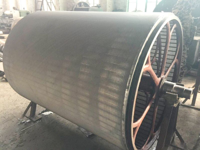
2.3 macroscopic examination
2.3.1 surface macroscopic examination:
(1) Inspect the inner and outer surface cracks, corrosion, scratches, base material shedding, casting shrinkage and other defects of the dryer cylinder. Inspection can be carried out with the help of a magnifying glass of 5-10 times rotation of the cylinder block, with the focus on the location of inspection:
(1) the inner wall structure is discontinuous and the shape is abrupt.
2. Pouring the riser;
The circular arc transition zone of cylinder head and cylinder block.
Check whether the drain pipe and drain valve in the dryer are intact.
Check whether the balance block of cylinder block is loose or loose.
Check whether cylinder head bolts and manhole bolts are complete and intact.
Check the sealing condition between the cylinder head, the manhole cover and the cylinder body.
2.3.2 Geometric Dimension Inspection: Check only at the first comprehensive inspection, and then review only possible changes. (1) requirements for cylinder neck structure with cone neck transition:
The angle between cone neck and cylinder wall should not be less than 80.
2. The length of conical neck should not be less than 80mm;
3. Cone neck and cylinder and flange should be smooth transition.
(2) Structural requirements for cylinder block with arc transition: the radius of arc should not be less than 30 mm, and the transition should be smooth with cylinder block and flange. 2.4 Thickness Inspection: When the data is complete and there is no visible thinning, the thickness should be measured when there is no factory data for the first inspection or when the cylinder block is polished and repaired in a large area.
(1) Measuring method: Because of the particularity of the material of the drying cylinder made of cast iron, the suitable measuring method should be selected to make the measuring data reliable as far as possible.
(1) measuring the average thickness of the cylinder block by measuring the cylinder bore diameter in a fixed position.
(2) Thickness gauge measurement: using cast iron thickness gauge or special cast iron probe to measure, before measuring, with the same material as the dryer, thickness is close to the test block calibration thickness gauge calibration.
(2) The thickness measurement points are arranged according to the measured shaft length of the dryer cylinder, and at least three cross-sections are taken. Each section has four measuring points along the circumference, and each dryer cylinder has at least 12 measuring points.
2.5 Cylinder Strength Check: For the cylinder and cylinder head thinning caused by cracks, scratches, corrosion and other reasons that need to be polished and eliminated, strength check should be carried out according to the relevant standards:
The formula for calculating minimum wall thickness of dryer cylinder block is:
The minimum wall thickness is calculated by the following formula: [delta]= K*P*R/[_]+C: P working pressure (MPa) R cylinder radius (mm) [_] allowable stress to HT200 [_]= 20MPa to HT250 [_]= 25MPa to HT300 [_]= 30MPa K stress increase factor, take 1.2 (including the temperature difference load caused by the thermal stress inside and outside the dryer cylinder) C corrosion Margin (mm) because the design thickness of the cylinder is much larger than the calculated thickness, the outer surface of the dryer should be based on tolerance matching, process requirements; the inner surface of the dryer should be polished with a smooth transition, without causing greater stress concentration and temperature difference.
(2) The thickness of each part of the cylinder head should not be less than the thickness of the cylinder head flange, the minimum thickness of the cylinder head flange is as follows: when the working pressure is less than 0.5 MPa, the minimum thickness of the cylinder head flange is D0 800 1000 1250 1500 1800 2000 2500 3000 3660 3800 delta F1 3035 5560 68 when the working pressure is greater than 0.5 MPa, the minimum thickness of the cylinder head flange is D0 800 10001 68. 250 1500 1800 2000 2500 3000 3660 3800 delta F1 30 35 40 50 60 70 763. Record and report collation and filing according to "Pressure Vessel Periodic Inspection Process"